Arc Flash Hazards (NFPA 70E)
- njmechler
- May 24, 2022
- 4 min read
Basics - The danger most people associate with electrical systems is shock: You touch a wire and a metal frame and experience a jolt of electricity. There is another related safety issue that can be just as dangerous, an arc flash. Arc flashes are the light and heat produced by an arcing fault, a short circuit where ionization occurs. Personnel in the presence of an arc flash event can be killed without ever coming into contact with an electrical current due to the arc blast. These two terms are technically separate, but for the remainder of this article we will refer only to "arc flash".
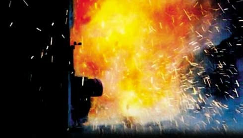
A Photograph of an Arc Flash Event (Source: Schneider Electric)
NFPA 70E, the Standard for Electrical Safety in the Workplace lists extensive requirements for mitigating the risk of arc flash events. In particular, personnel working on energized electrical equipment must wear proper personal protective equipment (PPE). Working on energized equipment means performing electrical maintenance without disconnecting all possible sources, a dangerous practice that should only be done by highly qualified individuals when absolutely necessary. People working in the proximity of energized equipment may be exposed to arc flashes. Therefore, in addition to risks from dangerous voltages, PPE must be rated to withstand the incident energy, usually in units of cal/cm^2.
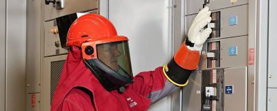
A Worker in Arc Flash PPE (Source: Honeywell)
Once the incident energy becomes large enough, the required PPE to wear may become impractical. In these cases, no energized work should be performed. If energized maintenance is necessary, additional mitigation techniques must be employed, such as arc-resistant equipment and advanced arc-flash detection schemes (more on this below).
In addition to understanding the potential incident energy during an arc flash event, we also need to know the arc flash boundary. The arc flash boundary tells us the distance at which we are "safe" during an arc flash event. The incident energy at the arc flash boundary is low enough (1.2 cal/cm^2) that unprotected individuals would only receive second degree burns. Maybe "safe" isn't the right word, but chances of death at this distance are very low.
Arc Flash Hazard Analysis - The simplest way to determine the level of PPE necessary is by taking information directly from tables provided in NFPA 70E. This method is referred to as the "PPE Category" method. Using the category method, the PPE required is based on expected fault clearing time, available fault current, and the working distance. The PPE Category method covers a wide range of conditions up to 40 cal/cm^2 incident energy.
The more sophisticated approach calculates the incident energy directly. Instead of offering discrete options for PPE, incident energy calculations allow us to determine exactly what level of protection we require. There are a variety of calculation methods to use, the most important of which can be identified in Annex D of NFPA 70E. Three common methods are referenced here:
DC Maximum Power Method: Applies only to direct current (DC) circuits 1000V and below
Ralph Lee Method: Applies to alternating current (AC) systems across all voltages, Results become especially conservative over 600V
IEEE 1584 Method: Applies to 3-Phase AC systems rated 208V to 15kV, Additional requirements on the conductor gap distance and the available fault current are also included
IEEE 1584 is often incorporated into software packages that can complete arc flash hazard studies, but we will focus on the Ralph Lee and DC Maximum Power Methods here. The underlying principle of both calculations is an assumption that the available incident energy is equivalent to the maximum transferred electrical energy during a fault. Ralph Lee applies to AC systems while DC Maximum Power applies to DC systems.
For the Ralph Lee Method, the relevant equations are as follows:
E = 793 F V t / (D^2)
B = √( 2.65 Sf t )
Where:
E is the incident energy in cal/cm^2
F is the fault current in kA
V is the line-to-line system voltage in kV
t is the arc duration in seconds
D is the distance from the arc source in inches (also known as the working distance)
Sf is the bolted fault apparent power rating in MVA
B is the arc flash boundary in feet
The equations above are simple to apply, but first we need to determine the bolted fault current F and the clearing time t. The bolted fault current is the results of a short circuit study. The fault clearing time is determined by comparing the bolted fault current with the trip curves of the upstream overcurrent protection devices. NFPA 70E provides some recommendations on clearing times, but a detailed analysis in accordance with manufacturer data and actual system settings is necessary to get an accurate assessment.
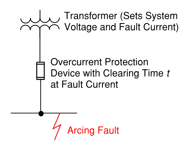
The Key Components in an AC Arc Flash Event
The equations for the DC Maximum Power Method are similar to the Ralph Lee Method:
E = .000775 F V t / (D^2)
B = .00212 √( F V t )
Where variables have the same definitions and units as described for the Ralph Lee Method. Determining the fault current F in a DC system requires a detailed understanding of the source and its limitations (whether the source is a batter bank, solar modules, or something else).
Arc Flash Mitigation Techniques - The incident energy from an arc flash is directly proportional to the time it takes to clear the arcing fault. Overcurrent protective devices operating in their instantaneous region may still operate too slowly (especially if there is a time delay for coordination) to clear the arcing fault quickly. The result can be extremely high incident energy levels, perhaps with PPE requirements beyond any reasonable limit. There are several ways that this problem can be mitigated:
Utilize a dedicated arc flash detection relay: These devices have sensors for light, temperature, or pressure in addition to typical overcurrent protection. Trip curves can be set based on these inputs, allowing for minimum opening times during an arcing fault.
Alter system impedances: Either a reduction or increase in upstream transformer impedance may help. When the upstream impedance is increased, there will be a reduced fault current that flows. Conversely, a decrease in upstream impedance may allow the fault to clear more quickly. Determining if a change in impedance will help requires coordination between trip curves and short circuit currents.
Switch to Arc-Resistant Equipment: Equipment like switchgear is sometimes offered in an "arc-resistant" variety. This means that the gear has been tested to a particular ANSI standard that minimizes the risk of arc faults. The specifics of how "arc-resistant" the equipment is should be discussed with the manufacturer.
Comments