
The Power Triangle
- njmechler
- Apr 25, 2022
- 4 min read
Updated: May 16, 2022
At its most basic, power is the product of a current and a voltage at any point in time. In other words:
Pn = Vn In
Where:
Pn is the instantaneous real power delivered to a load in Watts
In is the instantaneous current flowing through the load in Amperes
Vn is the instantaneous voltage across the load in Volts
This definition of power is universally true, but it's not that useful for the modern world's power systems. AC power in the United States alternates its voltage and current 60 times per second, so the particular power at any point in time isn't valuable. Instead, we like to know what happens over one cycle of the AC waveform, the average power flow:
P = V I cos(θ)
Where:
P is the average real power delivered to the load
V is the magnitude of the root-mean-square (rms) voltage across the load
I is the magnitude of the rms current through the load
cos(θ) is the power factor, where θ is the phase angle difference between the voltage and the current and cos() is the cosine function
The current, voltage, and power in the above equation are all straightforward to apply. When we're talking about the US power system, everything is reported in rms values (e.g. 120V, 208V, and 480V services are all rms values). But what about power factor? Power factor relates back to impedance. Recall that a complex impedance Z can be broken down into its resistance R and reactance X as:
Z = R + j X
The impedance, just like any other complex number can also be written in terms of a magnitude and a phase using trigonometry. The polar form of Z is:
Z = √( R^2 + X^2 ) ∠ atan( X / R)
Where ∠ is the angle operator for a complex number and atan() is the inverse tangent function from trigonometry. The angle of the complex number in terms of X/R is actually equivalent to the phase angle difference between the current and the voltage because of Ohm's Law. Thus:
Z = √( R^2 + X^2 ) ∠ θ
In short, the angle of the impedance is the same as the phase difference between the voltage and the current. The cosine of this angle is known as the power factor. The triangle below summarizes the relationships we've discussed. Only resistive loads can absorb real power. Reactive loads cannot. This is why the power factor is essential for determining how much real power is actually absorbed by a load. Currents and voltages could be huge, but if there's no resistance in the load to absorb the power, then no real work can be done by the load.
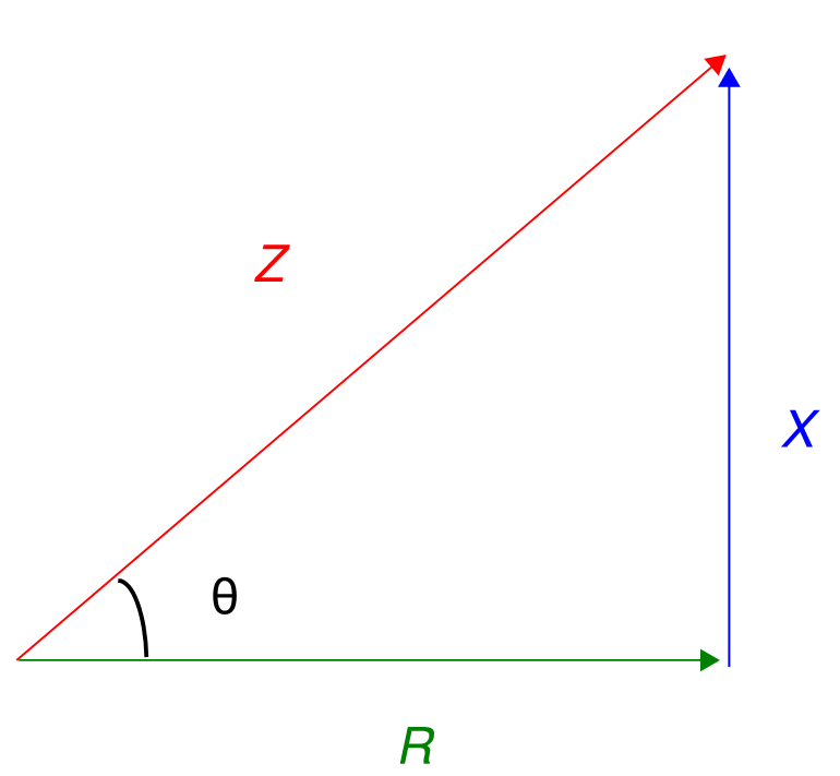
The Impedance Triangle and Power Factor Angle
What you likely realize by now is that real power doesn't tell the full story. If we know the real power a load is absorbing, that just tells us about the resistive component of that load. If we want to understand the reactive component of the load, as well as the total current flowing through the lines to feed that load, we need to define a new quantity. This is the reactive power:
Q = V I sin(θ)
Where:
Q is the reactive power, measured in Volts-Amperes-Reactive (the same units as Watts, but with a distinct name to make sure we understand the difference from real power)
sin() is the sine operator from trigonometry
V, I, and θ are the same variables from the real power equation above
Although reactive loads are not capable of absorbing real power like a resistive load, the idea of reactive power is very helpful for electrical designers. Understanding the reactive power allows us to speak about loads in terms of their power and mechanical work while still realizing that there's more to the story than just resistance.
We can combine the real and reactive power, just like resistance and reactance, to define a composite power, the apparent power:
S = P + j Q
Apparent power is measured in Volt-Amperes. Once again, the unit is technically the same as the Watt or the Volt-Ampere-Reactive, but a different name is given to help distinguish between the related quantities. The apparent power has the same phase relationships as the impedance triangle above. This means that the following relationship hold true:
P = S cos(θ)
Q = S sin(θ)
In words, the power factor can be defined as the ratio of the real power to the apparent power. The definition of power factor makes more sense this way. Apparent power is the product of the current and voltage, a statement on what the power flow in the system looks like. The real power is the actual real power that is being absorbed by the load. The power factor is just the ratio of the real to the apparent.
Typical Power Factors - Loads can be categorized into general power factor ranges based on the type of equipment:
Heaters will generally have a power factor near 1. Heating is done with resistive elements and therefore has little reactance required.
Induction motors running at their full load generally have a power factor of around .8. At no load, induction motors will have a much lower power factor, as magnetic effects dominate and no real work is done.
Synchronous motors can adjust their power factor to be unity, leading, or lagging.
Devices like reactors and capacitors are purely reactive. They have a power factor of near 0.
Transformers generally also have a power factor near 0, but this factor only matters during short circuit conditions, as transformers by themselves are not considered to be loads.
The power factor of lights can be all over the place based on the technology used.
Example: Consider a voltage of 277V is applied to a single-phase load with an impedance of 1+2j Ohms. What is the reactive power drawn by this load?
Solution: Start by drawing a picture:
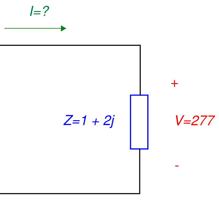
The first thing that we need to determine is the current flowing into the load. We can do this using Ohm's Law:
| I |= |V | / | Z | = 277 / √( 1^2 + 2^2) = 123.9A
Next, we can compute the reactive power using:
Q = V I sin(θ) = V I sin( atan(X / R) ) = 277 * 123.9 * sin( atan(2/1) ) = 30.7 kVAR
The total reactive power consumed by the load is 30.7 kiloVAR (kVAR for short).


Comments